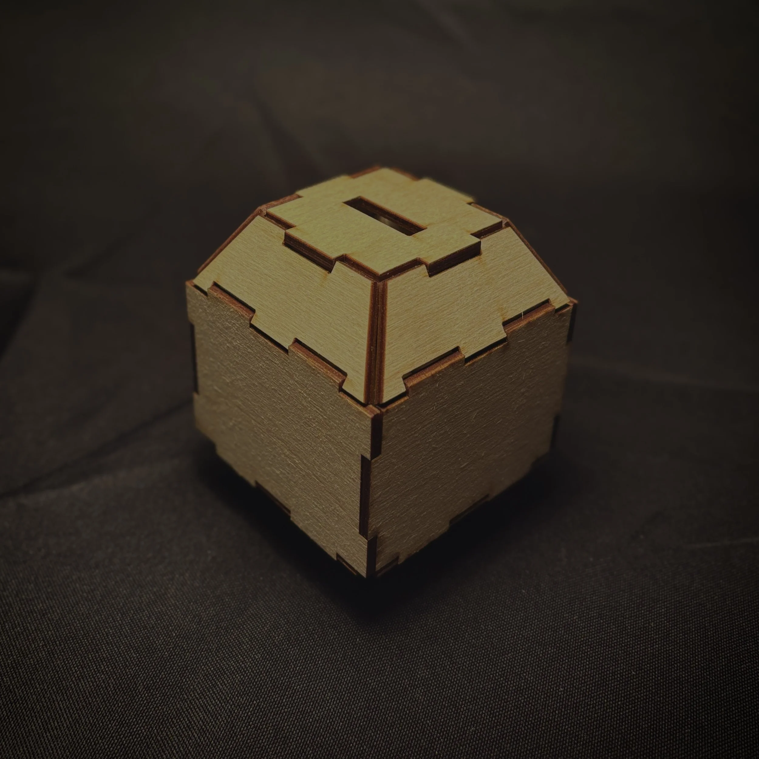
The Box
In this project I explored and learned the basic fundamentals of CAD, tolerances, kerf, and material analysis.
Constraints
No face orthogonal to all neighbors
No adhesives or fasteners
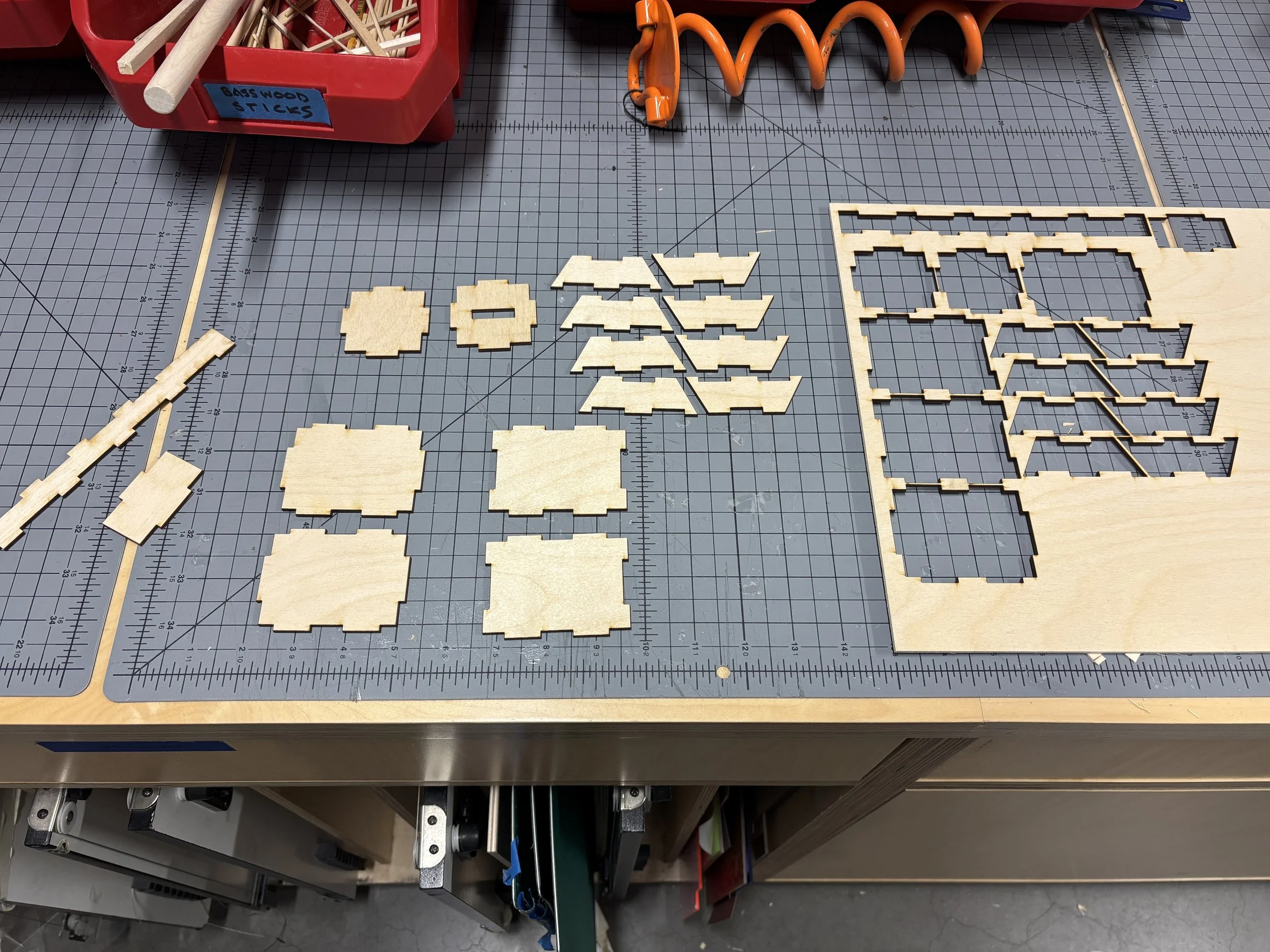
Material limited to 1 sheet of 12” x 12” birch plywood
Concept Ideation, Sketches, Prototyping
V1
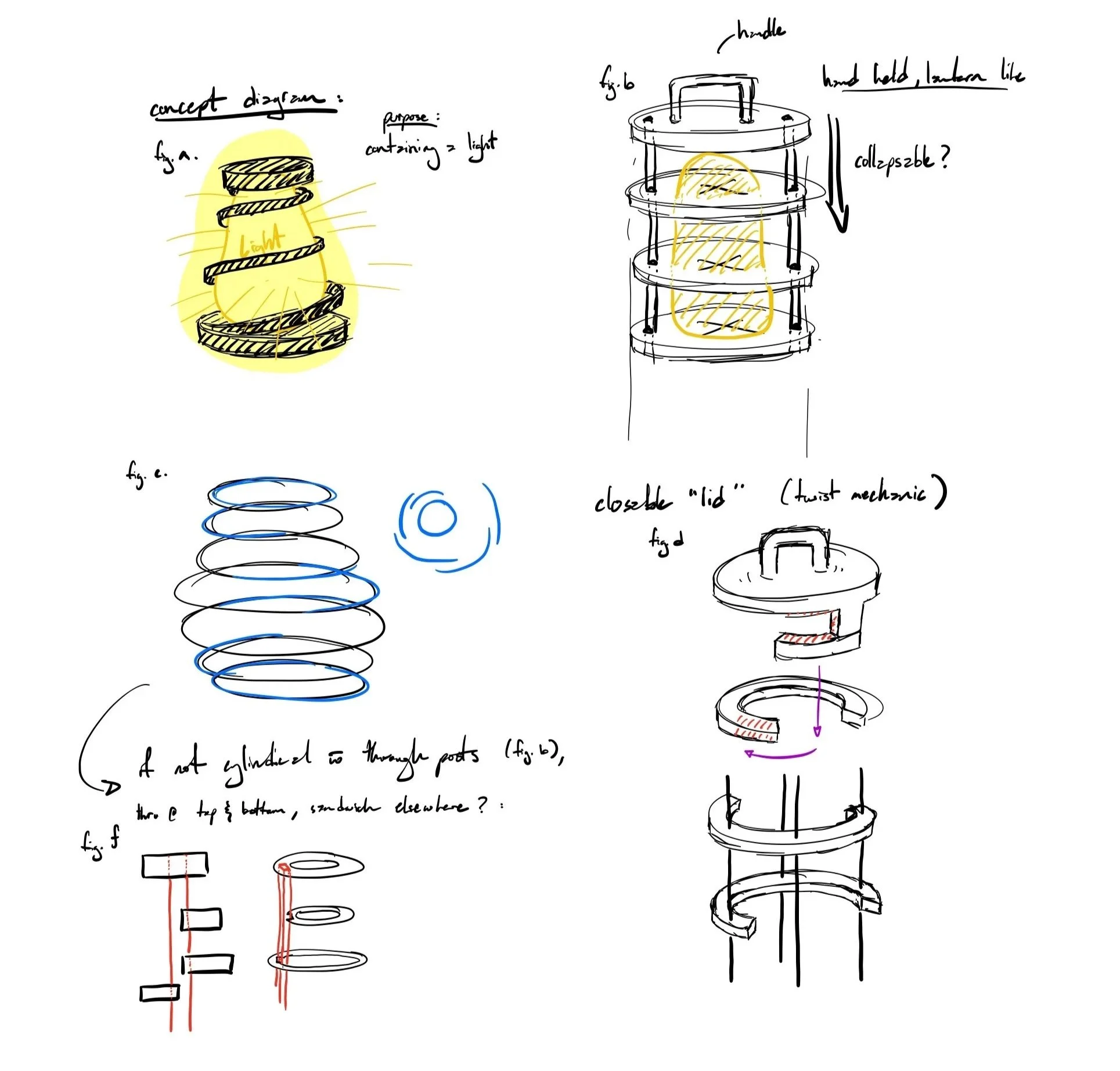
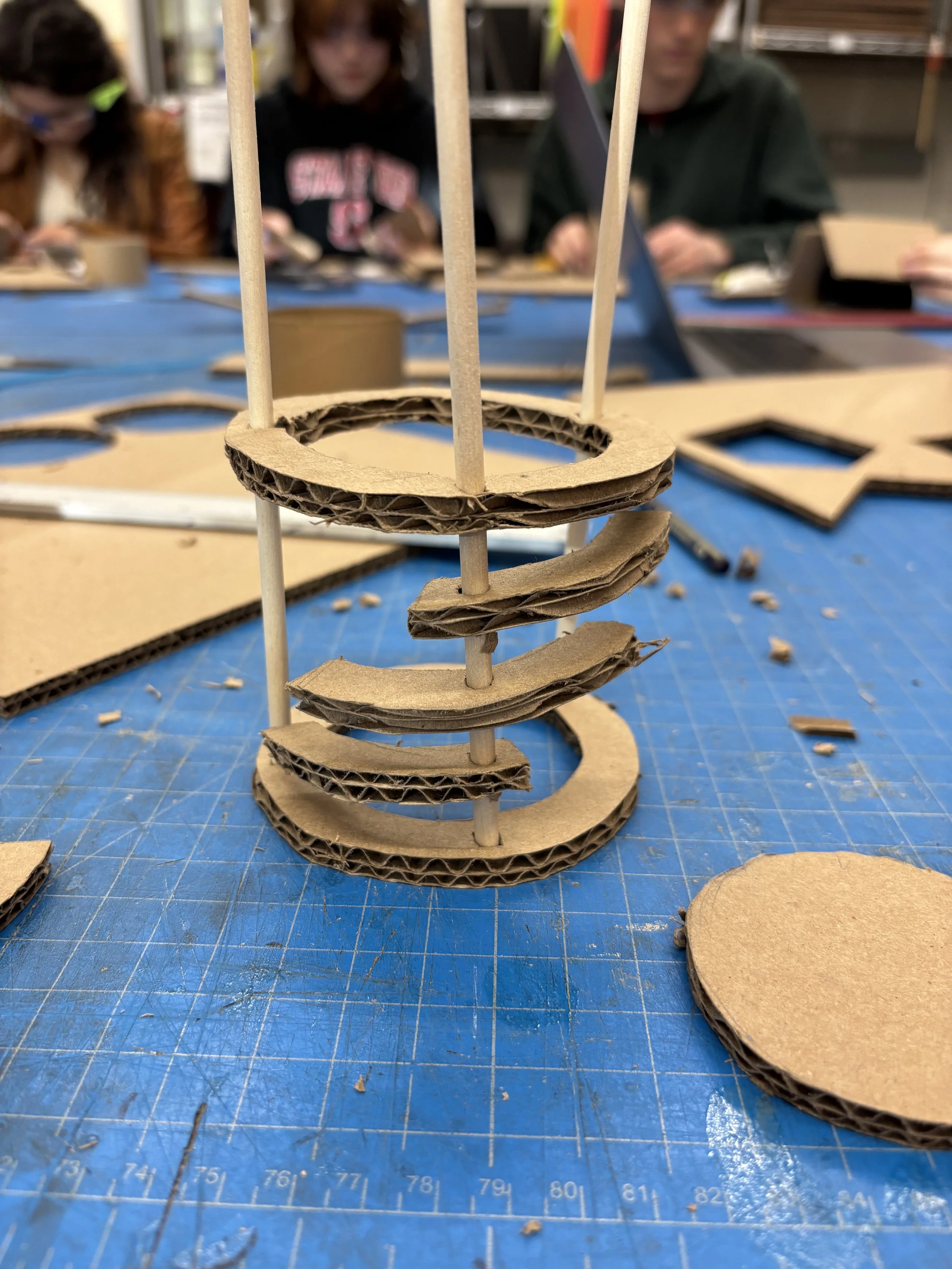
V1 Rough Prototype
V2
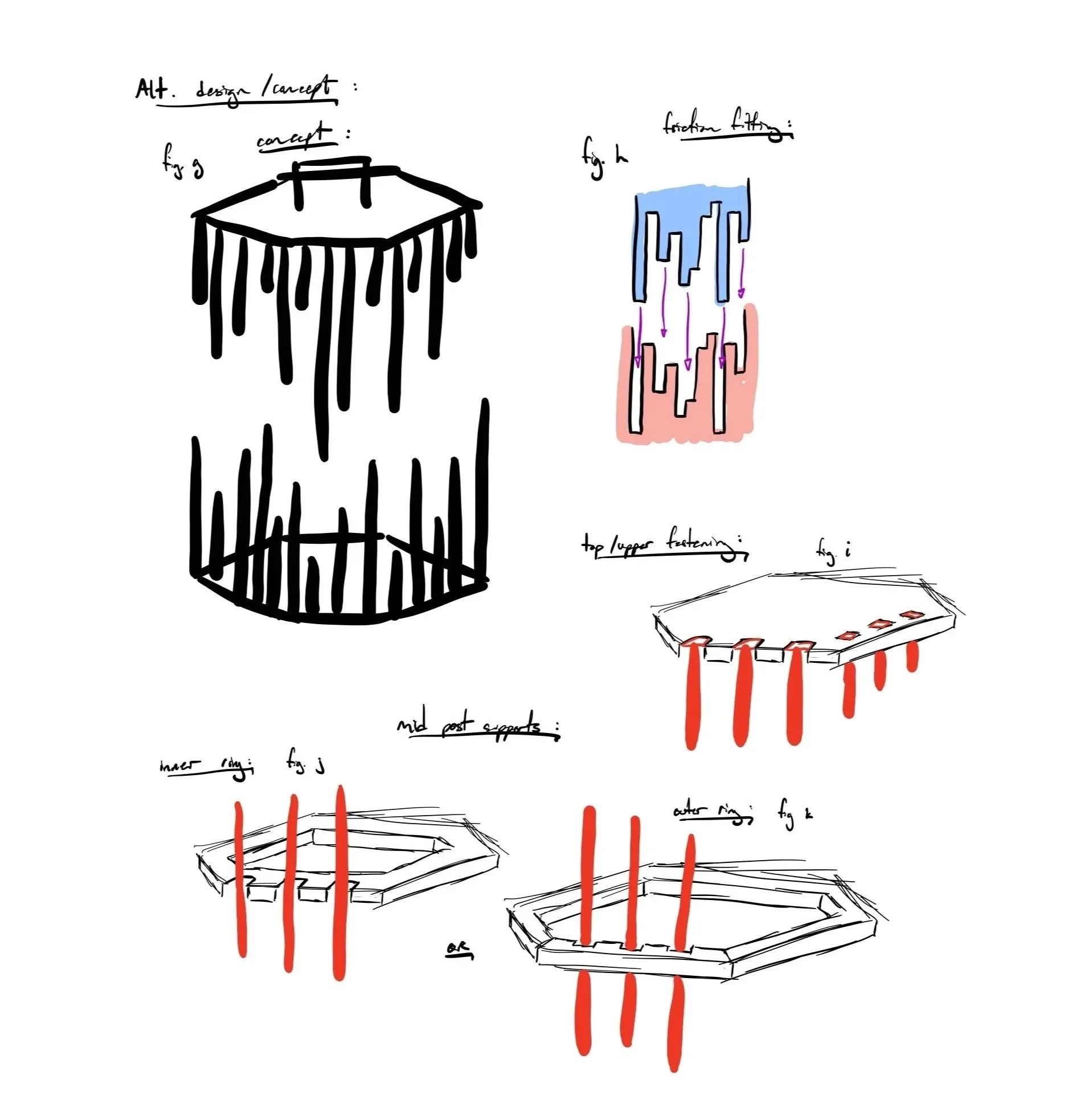
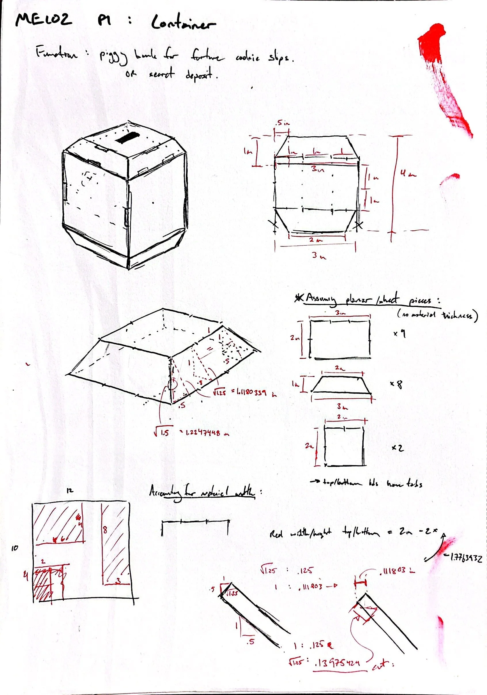
Original Concept Sketches and Prototype Issues:
Too complex (v1 and v2)
Structurally weak (v1)
Did not meet basic specs or orthogonality constraint (v1 and v2)
Inefficient use of material (v1)
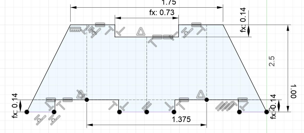
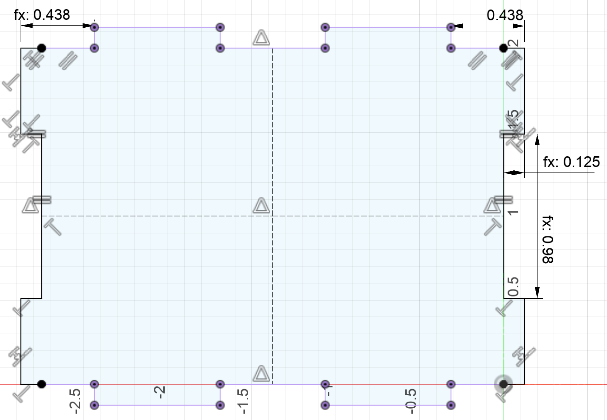
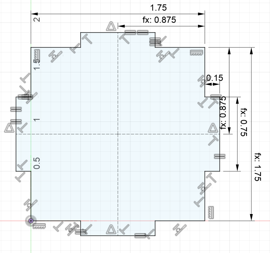
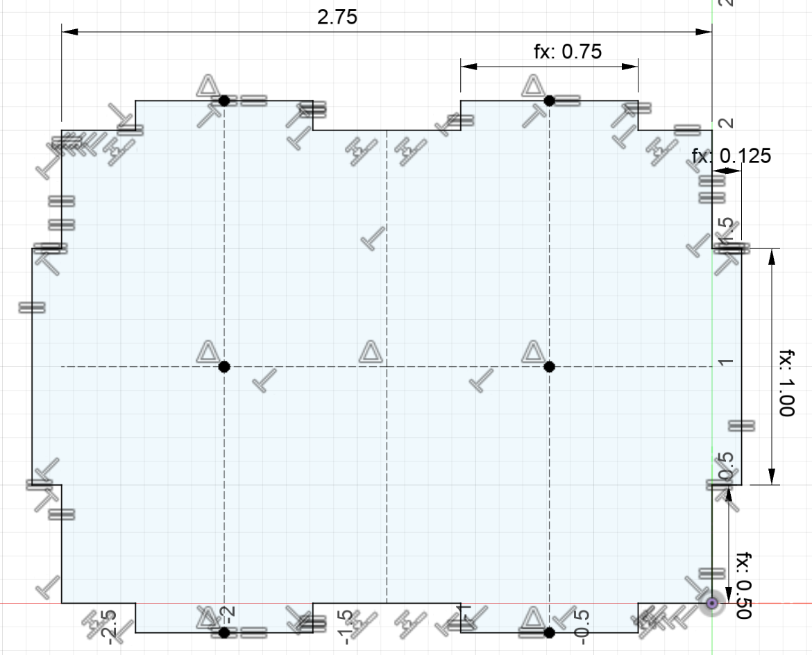
Revised Model Sketches
Concept sketched out by hand, then sketched in Fusion 360.
Friction Fits:
Interface/interference in CAD: +.02”
1” tab = .98” hole || .75” tab = .73” hole
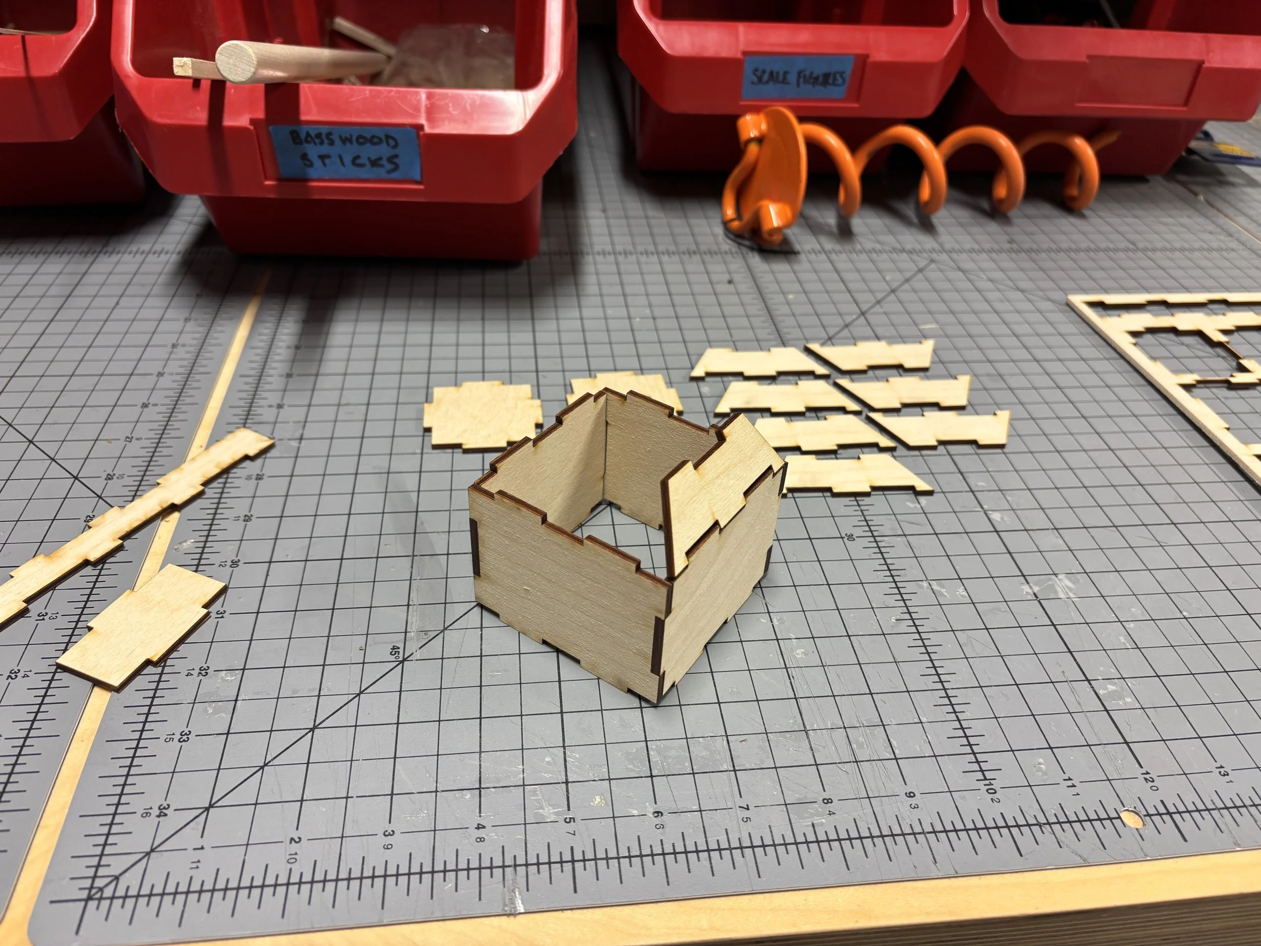
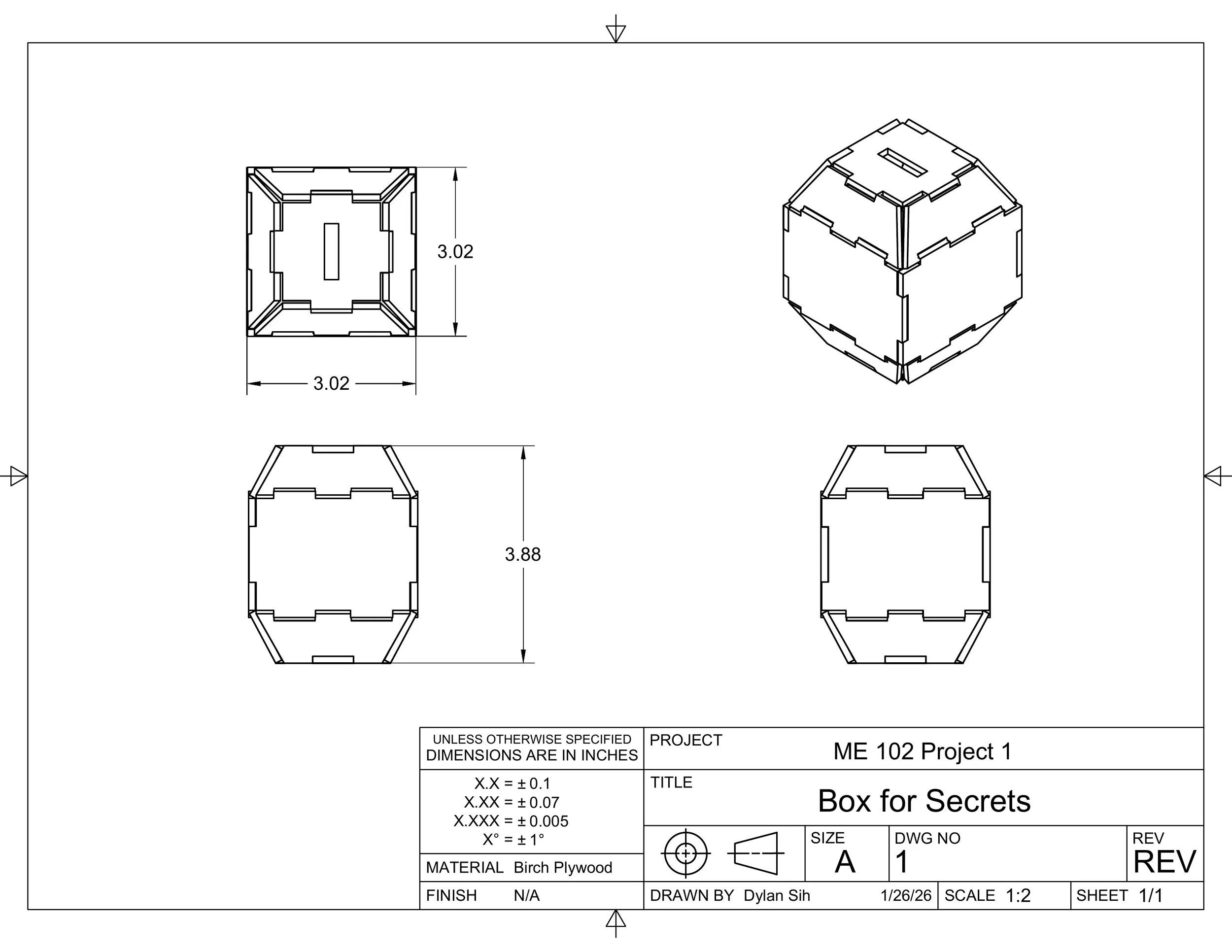
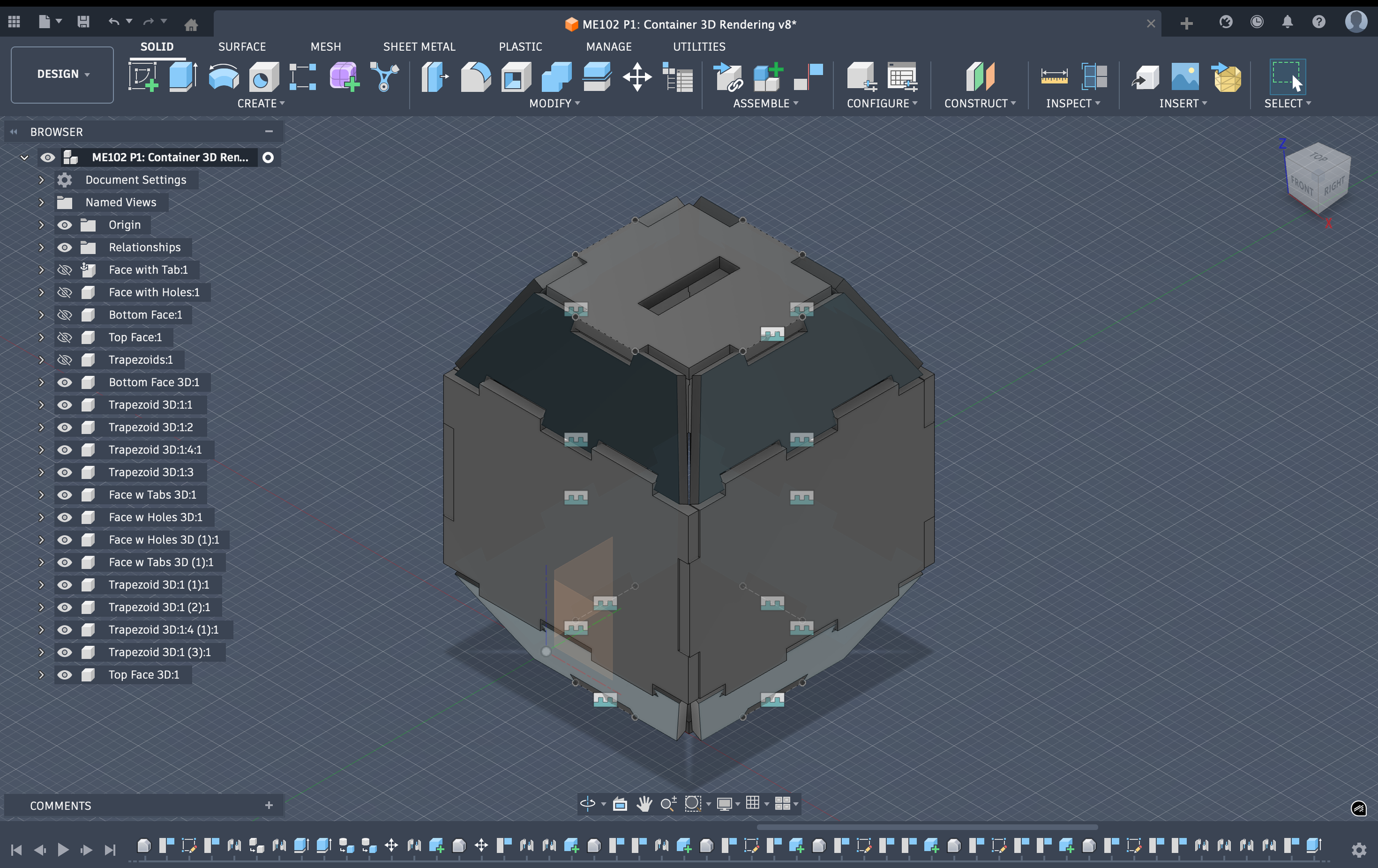
3D CAD Model
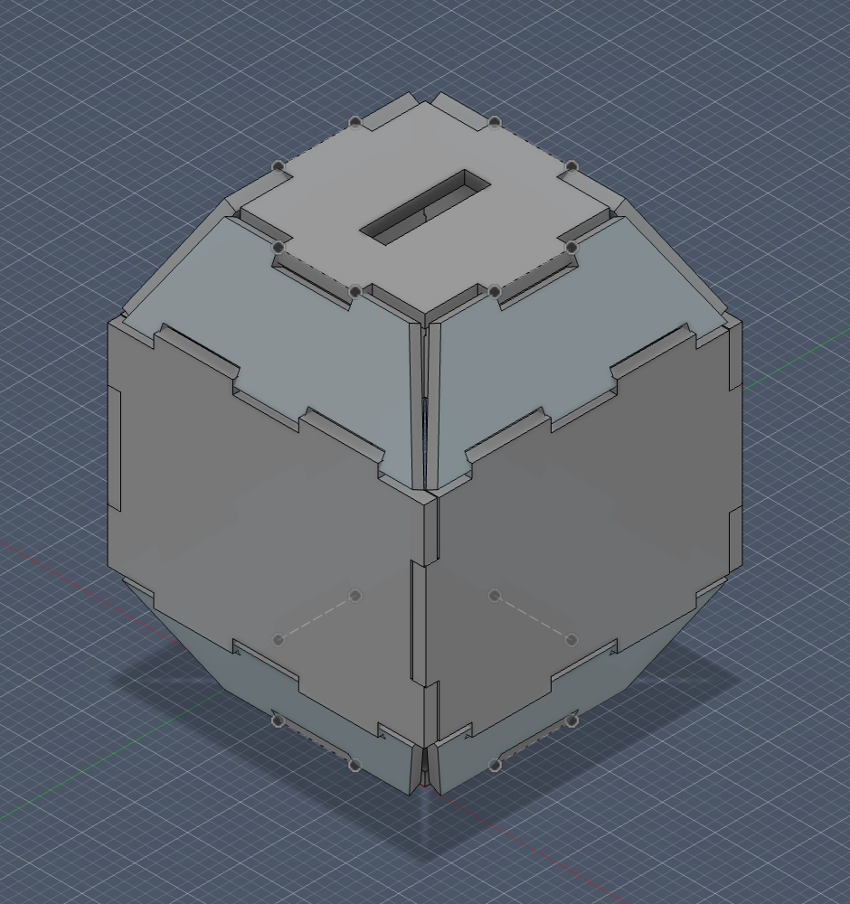
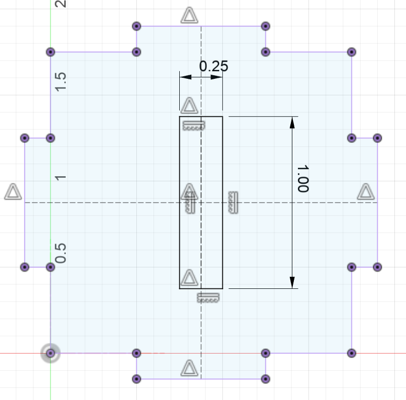
Build Process & Final Model
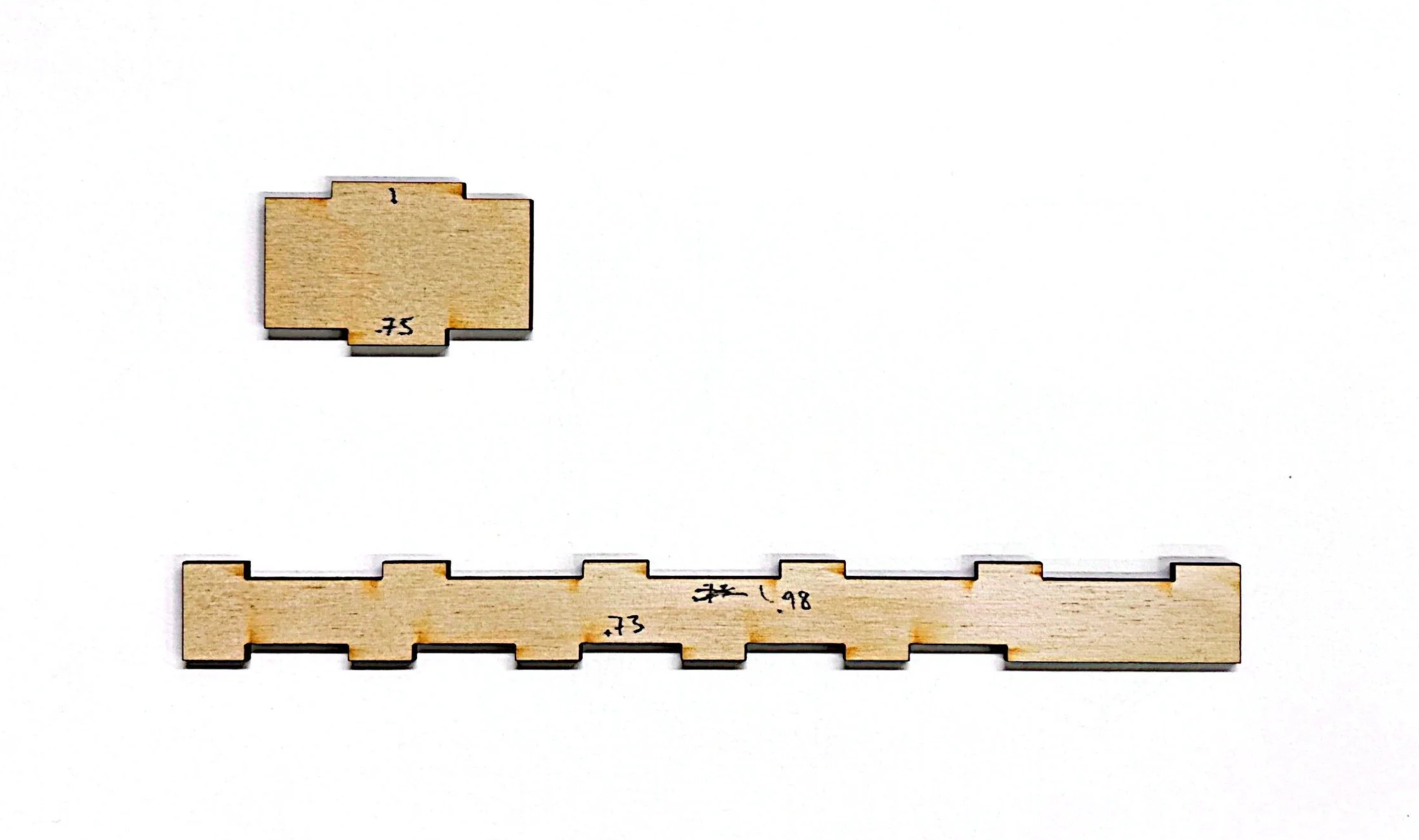
Test cuts:
Tolerance when cut (measured via caliper):
1” → .9850” and .98 → .9830” so: tolerance = +.002”
.75” → .7350” and .73” → .7330” so: tolerance = +.002”